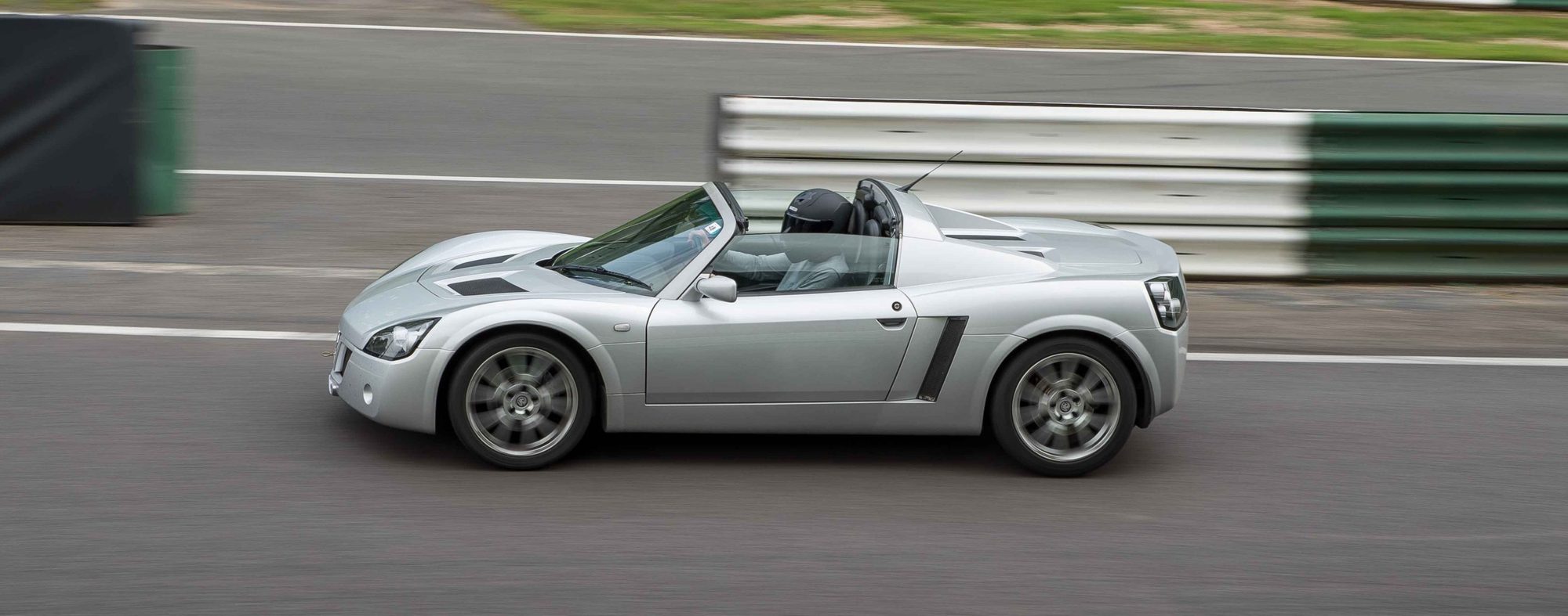
Turbo or supercharged? The detailed write-up, the charge cooler unit and the intake temperature readings are all from Turbo cars. Several 2009 owners and the 2015 pump wiring question were on supercharged (NA-based) cars. They used the same pre-rad, fans, header tank, pump and hoses, but the charge is cooled in the supercharger manifold's Laminova cores, not in a separate charge cooler behind the side intake. So the pre-rad, fan, sill, pump and header tank sections apply to both, and the charge cooler unit section is Turbo only.
On the Turbo, the kit has a pre-radiator with twin fans that sits under the main radiator, a charge cooler that goes behind the offside side intake in front of the rear wheel (where the turbo "ear" is), a header tank in the nearside rear corner of the engine bay, a circulation pump on the rear bulkhead, and silicone hoses that run along the offside sill. The original author said the quality was top notch, and that it was a bespoke kit made to fit the car, not a collection of parts. It is not difficult, but it is time consuming and awkward, especially alone. Another owner who fitted one the same month called it a very awkward and fiddly job, and said it was worth doing himself if you are hands-on, have a week, and want to save over £500. If you are not hands-on, he thought paying for the fitting was justified. In 2007 the maker quoted £500 to £600 for fitting.
What gets taken off first (Turbo)
- Remove the front clam, including the offside wheel liner.
- Jack the offside, remove the front and rear wheels and support the car on axle stands.
- Remove the offside turbo ear and the offside rear wheel arch liner.
- Remove the central under-tray.
- Remove the standard intercooler and all its rubber mounting bushes. Also remove the bracket held by the two clam joining bolts, then refit the bolts.
- Remove the radiator.
- Remove the driver's side sill trim and the cubby hole trim.
See Front clam removal. The sill trim is held by double-sided tape. Lay a piece of thick plastic sheet over the tape whenever you open the cubby hole, so the trim can go back on the original tape without it losing its stickiness. There are a lot of nuts, bolts and washers, so bag and label them as they come off. The author's view was that you need to, because you won't remember where each one goes.
The pre-rad and radiator
- Remove the radiator and cut the loom ties so the radiator housing can come out of the car completely. Offering the pre-rad up to the housing on the bench, upside down, shows exactly where the cuts go. The author tried to guess the cut positions from the maker's pictures on the car and made a mess of it, and said he would do it on the bench next time.
- The original radiator sits on a thick foam strip stuck to the plastic end cap on the offside. Remove it carefully, because you will use it later.
- Bolt the pre-rad to the radiator with the fixings supplied. The author fitted a Pro Alloy twin core radiator, and said the original could be used but would probably impair the system's efficiency. A 2009 owner of a 2001 car said the Pro Alloy radiator and pre-rad fitted "a treat", with no problems, apart from cutting up some foam lagging to fill gaps where there was no original foam. Another 2009 owner said the kit needed two pieces cut off the crash box, and that the radiator housing then sat out of line, which misaligned the clam. That matches the NA crash box supports below, so it was probably an NA-based car.
- Cut two holes in the offside edge of the housing for the pre-rad pipes, with enough clearance for the pipes and hoses. Fit the pre-rad to the housing with the bolts left a little loose, so you can adjust it. Put the housing on the car with a couple of the front bolts finger tight, and check the alignment.
- Fill the gap at each end of the radiator, between the end cap and the crash box, with foam. The author cut the original foam in half lengthways and stuck a strip on each side with double-sided tape, then sliced off another third when it proved too thick. The foam should compress enough to let the rear screw holes line up with the clips.
- Before you fit the housing for the last time, line up the three clips at the rear top of the crash box. The screws are hard to remove and refit. See the notes below.
- The three rear screws. The one by the ABS unit is the worst, with brake pipes round it. The author eased the pipes apart gently with a tapered piece of wood to get the tips of the pliers onto the head, then turned it a quarter turn at a time. To refit it, he hung the screw and washer from a thin piece of copper wire so he could not drop it. The other two are easier to reach.
- NA and supercharged cars: a 2009 owner fitting to an NA-based car found there are two plastic sections bonded to the crash structure that must come off, or the pre-rad cannot go in. These are not fitted to the Turbo. Another owner added that the radiator is carried by those supports, so you then need to support it on hard foam. The surround material is weak, and the standard closed-cell foam can be cut down to fit.
- Bolt lengths: a 2007 owner found the four pre-rad to radiator bolts in the kit are too short if you use the alloy spacers. He said you need at least 20 mm and used 25 mm.
- Lacquer: the author sprayed the front face of the charge cooler, which shows through the turbo vents, and the top and side of the header tank with clear lacquer before fitting, because bare aluminium dulls and discolours.
Stainless fixings
Both of the first two owners swapped the plated fixings for stainless, and cleaned and waxed the ones they kept. One said a three-year-old plated bolt from his own car looked terrible. The kit's maker agreed it was a good point and said they would supply stainless in future. This is one owner's amended list, all stainless, for about £3 at a fastener shop in 2007:
| Where | Fixings |
|---|---|
| Spal fans to pre-rad | 8 M6 nyloc nuts, 8 M6 flat washers |
| Pre-rad to main radiator | 4 M6 x 16 mm hex bolts (with a Pro Alloy radiator) or M6 x 25 mm (with the Vauxhall radiator), 4 M6 nyloc nuts, 8 M6 x 20 mm penny washers |
| Charge cooler, top | 2 M6 x 16 mm hex bolts, 2 M6 nyloc nuts |
| Charge cooler, bottom | 1 M6 x 16 mm hex bolt with an M6 x 20 mm penny washer, and 1 M8 hex bolt with an M8 x 25 mm penny washer. The M8 bolt looked longer than the 16 mm listed, so he bought M8 x 25 and M8 x 30 in case. |
| Header tank | 1 M6 x 30 mm hex bolt, 1 M6 x 16 mm hex bolt, 1 M6 x 16 mm button head bolt, 3 M6 nyloc nuts, 6 M6 x 20 mm penny washers |
Fan wiring and direction
The new Spal fans have blue and black wires, as does the original fan plug. The first author joined blue to blue and black to black, and tested the fans with an old battery and a sheet of paper on the radiator. They blew the paper off, so he assumed they were right. Several things then went wrong, in this order:
- A second owner connected blue to blue and black to black and found the fans blew the wrong way. He thought it might be luck of the draw with how the car was made.
- The first author then tested his own fans properly, by triggering them from the car, and found they were wrong too. The bench test with a battery had only shown the polarity he had assumed. Blade pitch matters as well as polarity, so only a real test on the car tells you.
- The fix, reported by several owners in 2007 and 2009, on both Turbo and supercharged cars, is that the blue and black wires cross over: the blue wire on the new fan loom goes to the black wire on the car loom, and the other way round. The easy way is to ease the two pins out of the original fan plug and push them back in the opposite holes, so the colours still match. The plug works like the pump plug, so the pins pull out.
- One owner said the Pro Alloy radiator's own wiring is a straight plug-in. That is the radiator, not the pre-rad fans.
The fan leads come out of the front. The leads on the pre-rad as supplied were on the front side of the housing, and the original fan connects through a hole at the rear, about a third of the way in from the nearside. The author turned his fans round so the leads came out the right side, which meant drilling a new hole in the housing for both leads (one was too short for the old hole). A second owner found the same thing. Taping over the old hole and replacing the grommet worked, though the grommet needed trimming. Fit stainless nyloc nuts and wax the fan studs while you are there.
Testing the fans. The coolant temperature sensor is on the nearside of the engine block, under a black plate that carries loom wiring, next to a square-headed block drain plug. Only the brass part is visible, and the plug is out of sight below the plate. Unplugging the sensor, or removing it, makes the fans run when the ignition is switched on, so you can see which way they blow. The author then found the fans stayed on all the time after he plugged it back in, and had to take out fuse 8 for 15 minutes to let the ECU reset. That is one owner's experience, so check the fuse numbering for your car before you pull anything.
Fan switch. One owner measured the pump at 0.88 amps in normal running, found each Spal fan is rated at up to 7.9 amps, and added a switch in the driver's cubby hole to run the fans by hand, tapped into the same supply cable as the pump. He said the temperatures fell as soon as the fans came on. He also planned to swap the 15 amp relay fuse for a 5 amp one, which doesn't obviously add up with two fans on the same supply, so work out the loads and fuse sizes for your own wiring before copying it.
Hose holes and the sill
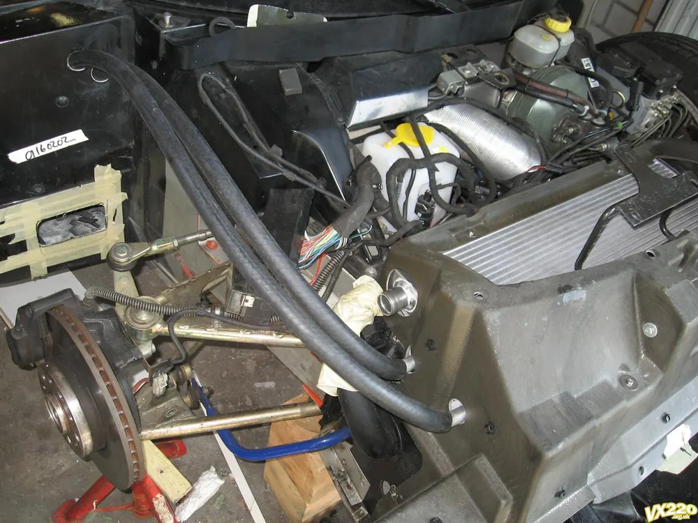
The hoses run from the front wheel arch, down the offside sill, to the rear. The kit instructions specify 34 mm holes at the rear of the offside front wheel arch, and the author used a 35 mm hole saw, which made no difference. His measurements, which are hard to follow without the lost diagram: the centre of the first hole is 75 mm from the bulkhead edge, the second hole is 50 mm further along (125 mm from the bulkhead), and the centre line of both holes is 75 mm down from the top of the sloping bulkhead, measured down the second hole's vertical line. Grease the edges with silicone grease and seat the two grommets (28 mm inside diameter, 9 mm thick, 43 mm outside) so the groove sits on the bodywork.
The foam. Inside the sill there are two blocks of dense foam, at right angles to the cavity, that completely block it. The brake pipe, the radiator supply pipe and the traction control wires (if fitted) also run in there. The author pushed a piece of old plastic conduit down the sill, past the foam, with a sharpened end and two screws screwed in half way as a cross at the other end, and pulled it through from the rear. He had to do this three times to clear it. The foam is tougher than it looks and has to be pushed to one side, not broken. Use the mirror and torch to look down the sill and check the conduit isn't fouling the brake pipe.
Owners fitting the kit in 2009, mostly to supercharged cars, did it differently, and there was no agreement on the best way:
- Through the front blind grommet. One owner found a blind grommet of about 14 mm at the bottom of the front of the sill. He took it out, pushed the foam aside with a length of dowel, reached down from the rear arch to move the second block, then pushed old tube along from the rear and threaded the hoses through. He called it one of the easier parts of the job.
- Cutting an access hole. Another cut a hole in the sill end to get a straight run, and closed it again afterwards with epoxy. A third cut 51 mm holes in the sill end faces, hidden deep in the wheel arches, and planned to close them with rubber inspection grommets. He cut the foam with a piece of aluminium pipe with nicks cut into the end, twisted by hand, then enlarged the hole with a hacksaw blade taped to a stick.
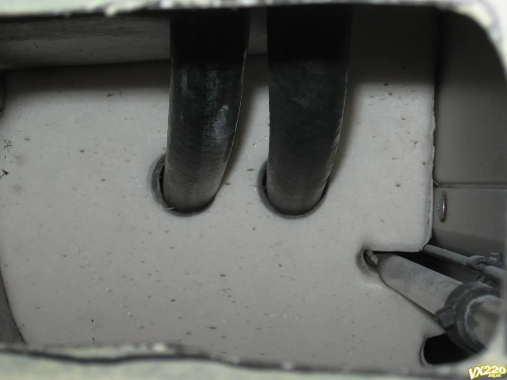
- Melting the foam. One owner didn't want to demolish the foam, which he said is not the strongest part of the car. He heated a thin-walled pipe with a torch and melted round holes through the front block, then did the same with a longer thin tube for the back block. He used that tube to pull the hoses through. Test the temperature on a piece of polystyrene first. The photo below shows the finished holes.
- Taking the sill cover off. This is only needed to pull the hoses up to the two top holes. It is held by two screws and a pull, unless it has been stuck down with sealant. One owner said heating the aluminium behind the joint lets you slice through the glue, lubricating the blade with WD40 or silicone spray, and one owner mentioned paying about £120 for a new sill cover. A side benefit of a bigger access hole: one owner took three stones and a hair clip out of the sill and said the rattles under acceleration and braking stopped.
Pump power
The pump should only run with the engine. How owners wired it, in the order they reported it:
- Battery feed and a relay, switched from the fuelling circuit (2007, Turbo). The author ran a fused positive and a negative cable from the battery, through the sill with the hoses, because he didn't know the pump's current draw. The pump has no wattage or amps on it or on the box, and the maker confirmed 17 amp cable was adequate. The relay is switched from the red/grey wire in the blue connector block behind the coolant expansion tank bracket. The kit-sheet guide has the terminal numbers and the full procedure. This circuit stays live for 45 seconds after switch-off, but only if you have started the engine. Turning the ignition on and off alone gives five or six seconds.
- Fuse box and boot relay (2009, supercharged). One owner took the live feed from the battery through a new fuse in the fusebox and the relay slotted into one of the spare relay positions in the boot, and spliced the switched live into the fuel pump feed. He soldered the pump and relay earths into the ground wire before the chassis earth point in front of the pass side rear wheel. He said this looks more factory.
- The fuel pump relay coil wire (2015). A supercharged car owner asked for best practice for a pump that runs whenever the ignition is on. The replies don't say which engines the other owners had, but two said most people use the fuel pump feed, so the pump runs for a few seconds while the fuel system primes and then stops until the engine is started. A third said to use the white/violet wire that feeds the fuel pump relay coil to feed the charge cooler pump relay coil as well. That is a single post from an owner on one car, so check it against the wiring diagrams and with a meter before you cut into anything.
The author's relay had a 30 amp fuse that he replaced with a 15 amp one. Another owner planned a 5 amp fuse (see the fan switch above). Neither figure is confirmed, so decide the fuse value from your own wiring.
The charge cooler unit (Turbo only)
This is for the Turbo kit. A supercharged car has no separate charge cooler unit, because the Laminova cores in the manifold do that job.
- Bolt the black angled bottom support to the subframe, just tight enough that it can still be moved with some effort. This lets you fine-tune its angle.
- Put the charge cooler in from the front through the rear wheel arch. It may need to go in and out a couple of times, and the fit is snug. The author had a moment of doubt about whether the rear clam needed to come off, and it didn't. His first fit fouled the top turbo ear retaining screw, which he trimmed back by about 3/8 inch.
- Fit the top rear bolt nearest you, using a plain nut for the trial fit so it runs on and off quickly, then adjust the cooler in and out and adjust the bottom bracket angle from the turbo ear opening until the bolt threads.
- The author's bracket angle was slightly out, so he bent it a little in a vice, and used a couple of washers as shims to close a very slight gap that would have distorted it when tightened. Another owner's bracket was bent in transit. Expect small variations.
- With the cooler out of the way, tighten the bracket to the subframe without moving its angle (he marked a line against the subframe), then fit the cooler, connect the push sensor on top (its lead was too short, so he cut one cable tie holding it to the loom) and tighten everything.
- Push the supply hose at the front of the cooler down into the sill to leave leeway, mark it against the inlet, cut it, and push it on with the hose clip in place. A very thin smear of silicone grease on the outside of the connection makes this easier. Refit the air hoses on top and bottom.
Header tank, pump and hoses
- Header tank. Fit it after the relay connection, because the connection can't be reached once the tank is in. It goes in the nearside rear corner of the engine bay. Remove the two bonnet stay bolts and use the longer bolts supplied. It is a snug fit, and you may have to push the standard coolant tank bracket slightly. The tank has a bottom flange with a hole: make a hole through the boot bulkhead with a bradawl from the engine bay side, find it from the boot side, and enlarge it for the fixing bolt and washers.
- Gearbox breather pipe. An owner pointed out in 2008 that once the tank is in, refitting the gearbox breather hose is a pain, so fix it securely first. If you need to remove the tank later, drain the charge cooler system first. The tank also sits close to where the remote reservoirs of uprated dampers go in the boot, as one owner found.
- Header tank to pump. The shortest hose (1000 mm) goes from the pump inlet (the end opposite the electrical plug) to the header tank bottom outlet. Its length matters. The pump body (not the plug) should end up roughly in line with the corner of the boot, with room for the wires to turn at a right angle and go up. Cut it at least an inch long first, fit it, then shorten it.
- Pump to pre-rad. The supply hose comes up from the sill to the gap at the rear left of the charge cooler, then along the cooler's top air hose, alongside and slightly below it. Tie it loosely first. Its length is also important: the pump has to hang on it without touching the subframe below or the rear boot bulkhead. If it touches either, the vibration of the pump is hugely amplified and carried through the car.
- Padding the pump. The author stuck a piece of the spare radiator foam between the pump, the bulkhead and the subframe with adhesive, after cleaning the surfaces. Push it in beyond the vents on the pump's outer edge, because they appear to be for air circulation to the motor, and the foam must not block them.
- Return hose. From the rear bottom outlet of the charge cooler, it follows the pump hose up to the cooler's air hose, goes underneath it as it curves round, then rises diagonally beside the boot bulkhead to the header tank's top return connection.
- Front hoses. Push both hoses down into the sill before you measure, mark and cut. They loop up and over the front wheel arch liner, so cut them slightly longer than the tightest curve you could get away with. The author connected the pre-rad rear outlet to the charge cooler inlet because it was the shortest run. Another owner asked whether it matters which end is supply and which is return, and the answer given was only that the author had chosen the shortest run.
- Tape and tie. The pump plug sits just behind the wheel arch liner, where indirect moisture gets in, so the author taped over the connection itself. Mark the pump plug's + and - before taking the plug off to fit the pins, and fit the pins only after the pump is in its final position, so you can get the wire lengths right.
Hose quality. The first owner's kit had black silicone hose rated to 10 bar. One 2009 owner said his kit came with clear piping, which he said shouldn't really be used on a car. Another nearly ended up with clear hose too, and bought proper black radiator hose from an online hose supplier, which arrived the next day. Another said the header tank was almost as expensive as the cooler despite being a simple tank. These are second-hand reports about supply from that time, so check what came in your own kit.
Filling and bleeding
- Use extended-life coolant mixed 50/50 with water. If your area has hard water, use demineralised or distilled. The author used tap water, because his is very soft. He chose not to add a wetting agent, but said you could.
- Fill the header tank as far as you can. His system took 14 pints (about 8 litres) in total, but only after the pump had circulated the air out. The coolant return inlet protrudes into the tank and is a good level marker.
- With the cap off, turn the ignition on but do not start the engine. The pump will screech at first, because it is mostly pumping air. The author thought this couldn't be good for it, so ran it for only a few seconds at a time, remembering that it runs on for five or six seconds after the ignition goes off. Top up, and repeat.
- After two goes the pump began to grab fluid and got quieter, but there was still plenty of air. He then started the engine and switched off, leaving the pump to run on, and repeatedly blocked and unblocked the top return pipe with his fingers inside the filler hole to build back pressure and help the coolant circulate on release. That worked. It took repeated topping up.
- The pump gets noticeably quieter as the air goes. Carry on until the level stays steady, then top up again after the first drive, as with the main cooling system. See Coolant change and bleeding.
Putting it back together
The wheel arch liners need a little more care because of the new hoses, and access to the offside headlight retaining nut is now tight. The author had replaced the nyloc nuts on his headlights with ordinary stainless nuts and a split washer, which lets you run them down by finger and only use a spanner for the last turn, and another owner agreed. After that, drive the car and watch the temperature gauge, the coolant level and the charge cooler header tank.
What it weighs and how long it takes
- Weight. The author gave just under 40 lb (about 18 kg) for the system, about 57 lb (about 26 kg) with 14 pints of coolant. He said about 15 lb was offset elsewhere, but the car was still about 40 lb heavier, and he couldn't feel any difference in performance.
- Time. He took ten days on and off, including days he didn't work on it, and thought a competent person with instructions could do it in three days. In 2013 an owner said it took him about 12 hours. In 2008 two or three people started at 9am and stopped at 9:30pm with everything done except the pump electrics, the headlights and the trim, and finished the wiring a few days later. The author had said a day and a half was more realistic for two people.
What it did to intake temperatures (Turbo)
One 2007 owner logged intake air temperature with OBD software on a remapped Turbo, on the same stretch of road, before and after fitting. His readings:
| Run | Standard intercooler | Charge cooler |
|---|---|---|
| Hard acceleration, 60 to about 130 mph (maximum) | 79 °C | 27 °C |
| Just after leaving the strip, first landmark | 32 °C | 24 °C |
| Second landmark | 25 °C | 21 °C |
| Third landmark | 21 °C | 19 °C |
With the charge cooler, a run to about 140 mph peaked at 31 °C and dropped back to 21 °C within five seconds of lifting off. On an earlier run, he said he had seen about 67 °C at 130 mph with the standard intercooler. He noted that the evening of the after runs was slightly colder than the before runs, and said he didn't think that explained much. This is one owner, one car and one road, not a controlled test, and the readings are from the ECU's intake sensor.
Don't read the dash gauge as charge temperature. The first author noticed the dash temperature gauge read one degree lower afterwards and wondered about it. Other owners pointed out that the gauge only shows engine coolant temperature, not the temperature of the charge, and any change came from the uprated radiator.
Position. One owner asked whether the pre-rad, which sits under the main radiator, was in the best spot, and whether it should go right at the front behind the grille for more free air. The author's view was that it is a trade-off, with a much larger area than the grille opening, and twin fans to help.
Supercharged cars: the Laminova circuit
A 2009 owner fitting the kit's pre-rad and pump to a car with a dual-pass Laminova manifold asked what order the water takes. Two owners gave the same answer: header tank, then pump, then pre-rad, then the manifold (or charge cooler), then back to the tank. The reasoning given was that the pump heats the water slightly, so you put the pump first for the coolest water. One thought it made little difference, and the other used the same order for a better hose layout. For the dual-pass cores, water enters through the centre cores and flows out through the outer ones, and two of the Laminova cores need turning round to follow that path, with the small hole as the water inlet and the big slots facing the air gap. See the NA supercharger fit.