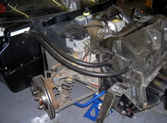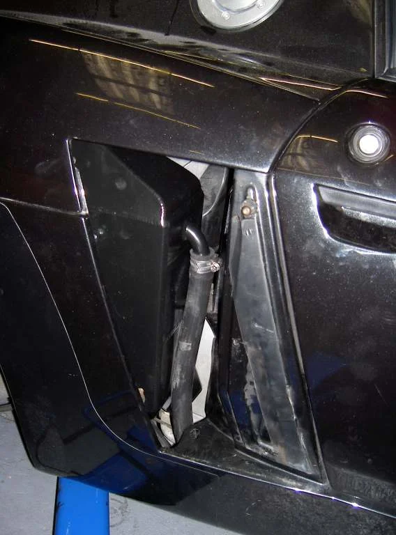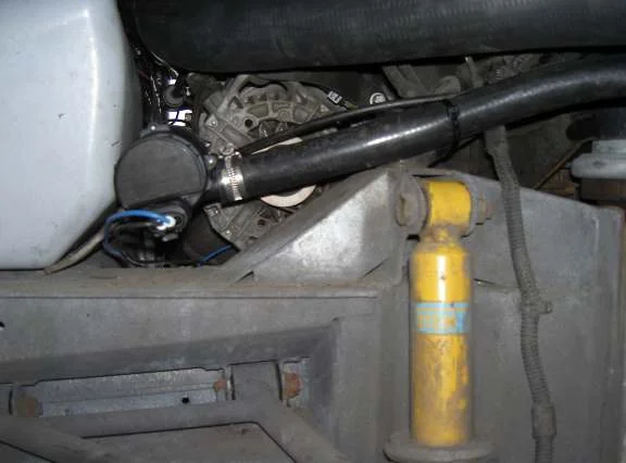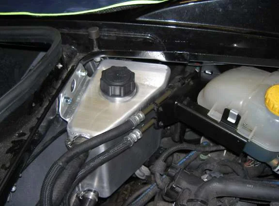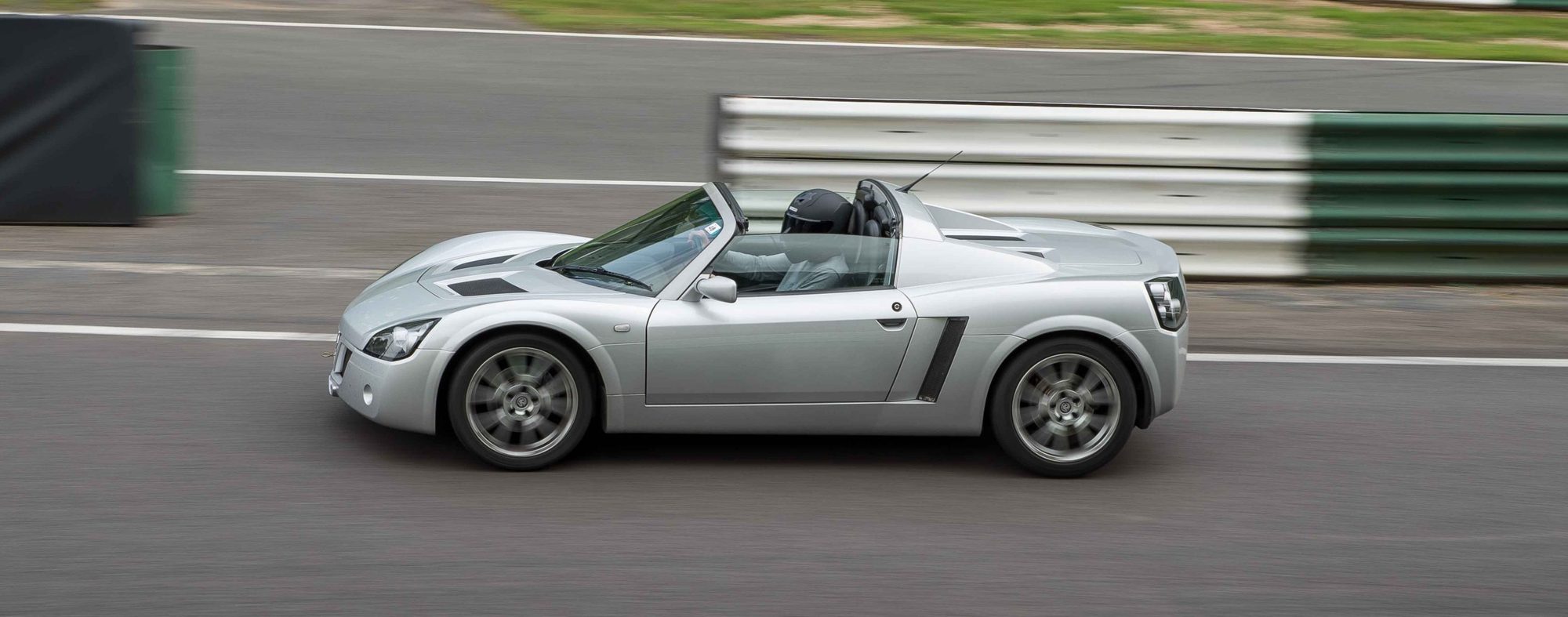
These notes describe a charge cooler kit for the Turbo, supplied by Courtenay Sport. They list the parts, which hose goes where, and how to wire the pump and the pre-rad fans. They don't describe the whole fitting step by step, but the photographs show the sill pipe run, the cooler and its bracket, the pump and the header tank. For how the Turbo's cooling circuit behaves and the upgrades owners have tried, see Turbo cooling circuit and upgrades. For the clam work, see Front clam removal and Rear clam removal.
What is in the kit
- 1 charge cooler unit and 1 pre-rad
- 1 water tank. Its plastic cap has the vent removed.
- 1 Bosch circulation pump, with the Bosch pump connecting socket (PAD12V-CON)
- 2 Spal 9 inch blowing fans, already fitted to the pre-rad
- 2 rubber grommets, 28 mm inside diameter, 43 mm outside, 9 mm thick. Use a 34 mm hole saw.
- 8 hose clips, No. 1A (22 to 30 mm)
Which hose goes where
| Hose (3/4 inch diameter) | Length |
|---|---|
| Forward charge cooler inlet to pre-rad | 3,000 mm |
| Pre-rad to circulation pump | 3,500 mm |
| Rear charge cooler outlet to the top water tank return fitting | 1,400 mm |
| Lower water tank outlet fitting to circulation pump | 1,000 mm |
Fixings in the kit
- Pre-rad to main radiator: 4 M6 x 16 mm hex bolts, 4 M6 Nylock nuts and 8 M6 x 20 mm penny washers. Add 4 alloy spacers (19 mm outside diameter, 6 mm hole, 7 mm thick) only if fitting to the original Vauxhall radiator. They aren't needed with a Pro Alloy main radiator.
- Charge cooler, top: 2 M6 x 16 mm hex bolts, 2 M6 Nylock nuts and 4 M6 x 20 mm penny washers.
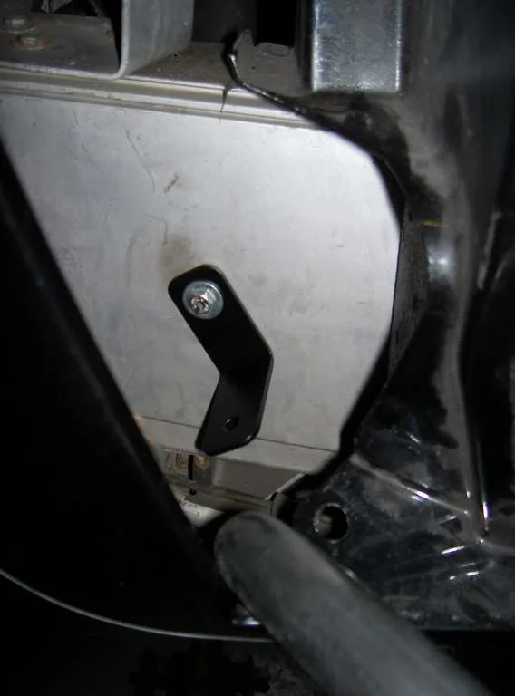
- Charge cooler, bottom: 1 M6 x 16 mm hex bolt with an M6 x 20 mm penny washer, 1 M8 x 16 mm hex bolt with an M8 x 25 mm penny washer, and a steel mounting bracket.
- Water tank: 1 M6 x 30 mm hex bolt, 1 M6 x 16 mm hex bolt, 1 M6 x 16 mm button head bolt, 3 M6 Nylock nuts and 6 M6 x 20 mm penny washers.
Pump wiring
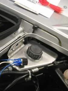
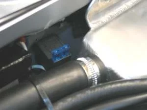
The relay is switched from the fuelling circuit. That circuit stays live for 45 seconds after the ignition is switched off, so the pump keeps the charge cooler circulating for that long after the engine stops. The feed comes from the blue connection block fixed behind the coolant expansion tank bracket.
- Remove the coolant header tank and its bracket if you can, as the blocks are hard to reach. Make this connection before the charge cooler header tank goes in.
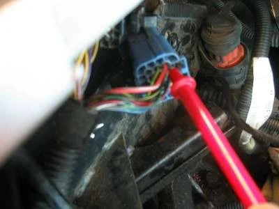
- There are two blocks: a black one on top, and the blue one you want below it. In the blue block, find the red wire with a grey stripe. It is thicker than most of the others, and is on the top (the side with the push-release catch), on the left-hand side of the wires entering the block from the rear of the car.
- Test it with a meter to check it stays live for 45 seconds after the ignition is turned off. This needs two people: one to test, one to switch the ignition. Turning the ignition on and off only keeps it live for five or six seconds. You have to start the engine and then switch off to get the 45 seconds.
- Connect it to terminal 86 of the relay. Rather than cutting the wire, strip a short length of the red/grey wire, bind the relay feed wire on, solder the join, and insulate it with tape.
- Mount the relay where it is protected from the weather: on the rear boot bulkhead near the top, under the lip to the right of the header tank (bulkhead centre). Run the feed wire around the corner by the ECU and secure it to the boot release cable sheath, which runs behind the header tank.
- Run the positive feed from the battery up and around the top of the rear wheel arch, and along the boot bulkhead from the offside to terminal 30 of the relay. Somewhere on this run (about the middle of the wheel arch) prepare the battery negative wire for the pump negative.
- Run a blue wire from terminal 87 to the pump positive, and a black wire from terminal 85 to earth. A convenient earth is on the left-hand side of the inlet manifold, viewed from the rear, about a foot from the relay.
- If your relay has an integral 30 amp fuse, change it for a lower value: 15 amp.
- Fit the header tank, pump and hoses before making the final connections. Wait to connect the relay positive and the battery negative to the pins in the pump plug until the pump is in place, so you can get the wire lengths right. Check which way round the plug goes against the + and - marked on the pump before you take it out to fit the pins.
- Tape everything up and tie the wires. The pump plug is just behind the wheel arch liner, where indirect moisture gets in, so the author also taped over the plug connection itself.
- Make the battery connections.
Fan wiring
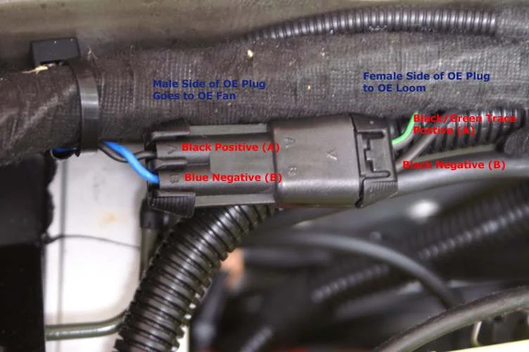
The two Spal fans have 2-pin connectors that don't fit the original wiring plug. The best option is to cut the connectors off the Spal fans, cut the original plug off the original fan (leaving enough wire to solder to), and solder the Spal wires to the original plug, with the polarity right. If you get it wrong, the fans will run the wrong way when they cut in.
- Spal fans: blue is positive, black is negative.
- Car side of the original 2-pin plug (female): positive is black with a green trace, and negative is black.
- Fan side of the original plug (male): a blue wire and a black wire, marked A (black, positive) and B (blue, negative). This is the opposite way round from the Spal fans.
Connect positive to positive and negative to negative. The black/green goes to the blue of the Spal fans, and the black goes to the black. Do not just join the blue and black from the original plug to the Spal fans without checking first, or the polarity will be wrong. The author suggests swapping the blue and black pins in the fan side of the plug, by carefully easing the pins out of the socket with a small screwdriver, so that blue is positive and black is negative to match the Spal fans. That is optional.
Solder every connection and insulate it with heat shrink, and check that nothing rubs or catches when the radiator assembly goes in.
Pipe run and mounting
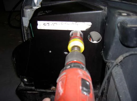
- Drill holes for the pipes to run along the sills. Be careful, as a water pipe runs behind the inside hole. The 28 mm grommets need a 34 mm hole.
- The charge cooler goes in with the steel bracket at the bottom. The pump is mounted on the chassis, offside rear, behind the wheel arch liner. The header tank is at the rear, by the expansion tank.