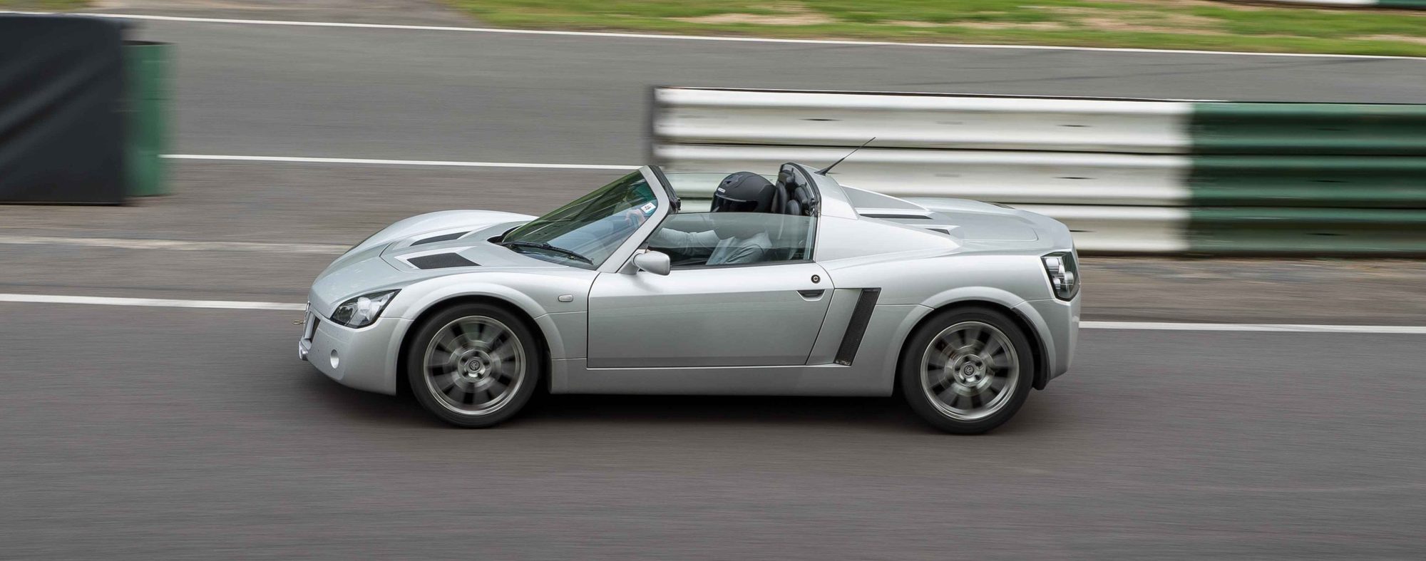
The NA page lists the engine on its own. To separate it from the gearbox once it is out see Gearbox removal with the engine out.
Engine removal and installation
NA (Z22SE) only.
Remove
- Detach the engine splash shield.
- Vehicle on 4–post ramp – other work performed on a (Vehicle on 4–post ramp – other work performed on a 2–post ramp.)
- Open the bonnet.
- Disconnect the battery. (Negative terminal)
- Open the rear engine cover.
- Remove the rear engine cover. (6 bolts)
- Remove the air intake pipe.
- 2 clamps
- Detach the fuel pressure regulator vacuum hose.
- Detach the intake air temperature sensor wiring harness
- 1 clamp. (From the cylinder head cover.)
- Detach the brake servo vacuum line.
- Unclip the brake servo vacuum line.
- Press in the retainer on both sides (arrows) and release.
- Place a drip tray underneath.
- Detach the oil supply line from the oil cooler. (1 union nut.)
- Detach the tank breather valve line. (Reposition the line to one side.)
- Disconnect the wiring harness connector from the lambda probe for catalytic converter monitoring. (Detach from the bracket.; Disconnect the wiring harness connector.)
- Detach the gearshift cables.
- Disconnect the gearshift cables with KM-6042.
- Reposition the gearshift cables to one side. (2 clips)
- Release the fuel pressure.
- Collect any escaping fuel in a suitable container.
- Raise the lifting ramp. (Half height.)
- Detach the rear wheels. (10 bolts)
- Remove the wheel arch trim panel. (12 bolts)
- Detach the wiring harness connector for the lambda probe for closed–loop mixture control. (Expose the wiring harness.; 5 clips, 1 retaining clip)
- Disconnect the engine wiring harness. (2 wiring harness connectors.)
- Disconnect the fuel lines. (Disconnect the fuel lines with KM-796-A.; 2 bolts; Reposition the fuel lines to one side.)
- Disconnect the wiring harness connector for the tank breather valve. (3 cable ties.; Reposition the wiring harness to one side.)
- Drain the coolant.
- Open the coolant drain plug at the coolant pump.
- Tightening torque 20 Nm
- Raise the lifting ramp. (Half height.)
- Remove the cover from the exhaust system. (9 bolts)
- Detach the lower heat shield. (3 bolts, 1 stud.)
- Remove the front exhaust pipe. (Remove from mounting.; 2 off)
- Unhook the gearshift cables. (Bracket on the transmission (arrow).)
- Unhook the hydraulic clutch actuation line. (Bracket on the transmission.)
- Detach the wiring harness to the alternator/starter motor. (1 wiring harness connector, 3 nuts.)
- Lower the lifting ramp.
- Detach the coolant hoses. (3 hoses; 2 hoses.)
- Detach the ground cable from the transmission. (1 bolt)
- Detach the high–pressure line with connection piece.
- Release the clip with a screwdriver in the direction of
- Slightly bend the clip together and insert it back into the
- Detach the left–hand engine damping block bracket. (3 bolts)
- Raise the lifting ramp.
- Disconnect the wiring harness connector from the reversing lamp switch.
- Remove the axle shafts.
- 2 off, 2 split pins.
- 2 nuts
- 2 bolts
- Use a support to take the weight (arrow), take out the (2 bolts, 2 nuts; Use a support to take the weight (arrow), take out the bolts.)
- 2 nuts
- 2 nuts
- Attach KM-904 with KM-6054.
- Set up on a hydraulic hoist.
- Undo the spigots of KM-6054.
- Attach KM-6054-4 to the cylinder
- Align the spigots, starting at the front right.
- Secure the spigots.
- Align the transmission support.
- Support the front end. (Use transmission jacks and square bars.)
- Remove the engine damping block bracket with the right–hand engine damping block.
- 3 bolts, 1 nut
- Take out the engine damping block bracket with the engine
- Remove the front engine damping block. (3 bolts, 1 nut)
- Remove the front engine damping block bracket. (4 bolts)
- Remove the rear engine damping block. (4 bolts, 1 nut)
- Lower the engine. Note: 2 technicians required
Install
- Raise the engine. Note: 2 technicians required
- Attach the rear engine damping block. (Tightening torque 86 Nm; Tightening torque 49 Nm)
- Attach the front engine damping block bracket. (4 bolts)
- Attach the front engine damping block. (Tightening torque 55 Nm)
- Attach the engine damping block bracket with the right–hand engine damping block.
- Insert the engine damping block bracket with the
- Tightening torque 85 Nm
- Tightening torque 45 Nm
- Take out the support for the front end.
- Detach KM-904 with KM-6054.
- Lower the hydraulic hoist.
- Detach KM-6054-4 from the cylinder
- Detach KM-904 and KM-6054 from the hydraulic hoist.
- Install the axle shafts.
- 2 off
- Insert the wishbone.
- Tightening torque 60 Nm (2 nuts.)
- Tightening torque 60 Nm (2 bolts)
- Tightening torque 60 Nm (Use a support to take the weight.; 2 bolts, 2 nuts)
- 2 nuts.
- 2 nuts.
- Tightening torque 120 Nm, undo, (Use new castellated nuts.; 2 off, 2 split pins.; Tightening torque 120 Nm, undo, tightening torque 20 Nm + 80°)
- Connect the wiring harness connector for the reversing lamps.
- Attach the wiring harness to the alternator/starter motor. (1 wiring harness connector, 3 clips)
- Attach the oil cooler oil return line. (1 union nut.)
- Hook the hydraulic clutch actuation line into place. (Bracket on the transmission.)
- Hook the gearshift cables into place. (Bracket on the transmission.)
- Attach the front exhaust pipe.
- 2 off
- Tightening torque 16 Nm (Insert into mounting.)
- At the lower heat shield. (Tightening torque 8 Nm)
- Attach the cover for the exhaust system. (9 bolts)
- Lower the lifting ramp. (Half height.)
- Connect the tank breather valve wiring harness connector. (Route the wiring harness.; 3 cable ties.)
- Connect the fuel lines. (Connect the fuel lines.; 2 nuts.)
- Attach the wiring harness connector for the lambda probe for closed–loop mixture control. (Route the wiring harness.; Attach to bracket.; Connect the wiring harness connector.)
- Connect the engine wiring harness. (2 wiring harness connectors.)
- Install the wheel arch trim. (12 bolts)
- Attach the rear wheels. (Do not tighten.)
- Lower the lifting ramp. (Half height.)
- Attach the left–hand engine damping block bracket. (Tightening torque 55 Nm (3 bolts))
- Attach the clutch operation mechanism. (The clip must audibly engage.)
- Attach the ground cable to the transmission. (1 bolt)
- Connect the coolant hoses. (3 hoses.; 2 hoses.)
- Attach the oil supply line to the oil cooler. (1 union nut.)
- Attach the wiring harness connector to the lambda probe for catalytic converter monitoring. (Attach to bracket.; Connect the wiring harness connector.)
- Connect the tank breather valve line. (To the intake manifold.)
- Attach the gearshift cables.
- Route the gearshift cables.
- 2 clips
- Attach the gearshift cables to the relay lever assembly.
- Attach the brake servo vacuum line. (To the intake manifold.)
- Attach the air intake pipe.
- Attach the fuel pressure regulator vacuum hose.
- Attach the intake air temperature sensor wiring harness
- 1 clamp. (To the cylinder head cover.)
- Tightening torque 3,5 Nm
- Attach the rear engine cover. (Check the alignment.)
- Attach the rear wheels. (Tightening torque 90 Nm)
- Connect the battery. (Negative terminal)
- Fill up with coolant and correct as necessary – see "Cooling System, Fill Up and Bleed.
- Bleed the hydraulic clutch actuation.
- See operation "Hydraulic Clutch Actuation, Bleed (F17/F23)" in
- Check and correct the transmission fluid level.
- See operation "Transmission Fluid Level, Check and Correct
- Attach the engine cover.
- Tightening torque 14 Nm (Check the alignment.)
- Close the rear engine cover.
- Reprogram the volatile memories.
- Close the bonnet.
- Attach the engine splash shield. (Vehicle on 4–post ramp.)
- Close the driver's door.
Owners' experience
Which way to take it out
- Engine alone. Several owners preferred this on a plain swap, as there is no reason to disturb the gearbox. It means stripping the engine first (see the list below) and splitting it from the gearbox in the car.
- Engine and gearbox together. Others said that with the rear clam off this is the better way, and one said that if you leave the ancillaries on, the gearbox has to come out with the engine. The driveshafts have to come out too. One owner described it as dropping the passenger-side lower wishbone and freeing the hub and driveshaft, and on the other side disconnecting the tie bar from the hub and swivelling it so the driveshaft slides out of the gearbox. The big advantage everyone gave is that you can strip and rebuild the engine on a stand or bench rather than leaning over the car.
- Gearbox out instead of the engine. For a clutch job one owner said this is quicker because the clam stays on, but it is hard physically and needs two trolley jacks, one to steady the engine and one to carry the gearbox. Another said that with a hoist, the engine is the easier way.
- Through the top with the clam on. One owner did it and said it is very close and he wouldn't recommend it.
What to take off first (engine alone)
One owner who had done several gave this list in 2009, repeated in 2012. It is a checklist from one person, so compare it with the TIS steps above.
- Battery disconnected, coolant and engine oil drained, and the charge cooler system drained on a supercharged car.
- Exhaust manifold, inlet system, fuel rail and injectors (tie the fuel pipes out of the way), starter motor, alternator and belt tensioner.
- Crank pulley. He said this is very important if the gearbox stays in place.
- Coil pack, to keep it from being damaged, and the engine loom disconnected from the engine (it can stay in the car).
- The oil cooler fitting and the lower oil pipe and fitting at the block, so they aren't damaged.
- The special oilway blocker in the oil filter housing (see below).
- Support the engine on a hoist, using the lifting brackets or straps under the engine. Remove the offside engine mounting alloy bracket and the bell housing bolts: two next to the exhaust, two above the gearbox, one above the starter motor and two under the engine.
- Move the engine, then lever it off the gearbox and lift it out. One owner said it comes out and goes back by moving the front of the engine towards the bulkhead; another, with the oil pump left on, said to push the front towards the front of the car as you lift. These conflict, so be ready to try both.
Another owner said he never touches the gearbox mounts, and just unbolts the engine and lifts it.
The water pump bolt, oil pump and chain cover
- One bolt of the water pump inspection cover hits the subframe. Taking it out gives about 5 mm more clearance. Owners who left the oil pump on said this bolt has to come out before the engine will lift clear.
- One owner takes off the oil pump and crank pulley as a matter of course, so the engine slides straight off the gearbox and lifts out. With the oil pump left on you have to twist the engine on the way in and out, which makes it hard to line up the clutch splines on refitting. The same owner said the chain cover can stay on, but it is easier to leave it off on refitting.
- Refitting that bolt. One owner's tip was to fit the water pump bolt first, through the chain cover, and then offer the pair up together. He said the easiest way is to take out the front and rear engine mount bolts and move the engine towards the bulkhead. His own method was to use a pick axe handle as a lever to move the engine about 30 mm, with gentle steady pressure between the subframe and the block, after loosening the front and rear mount bolts first. Another owner managed it with the engine on its mounts but said it was very tricky.
Mating the engine to the gearbox
One owner spent half a day unable to close the engine up to the gearbox without forcing it, even with the inspection cover and the long water pipe off. The fix, from another owner, was a little wiggle, and it went together within minutes. Don't force it, as that can damage the splines.
The oilway blocker in the filter housing
- The Speedster/VX220 has a small spring-and-clip piece inside the oil filter housing that blocks the original oilway. It sends the oil through the oil cooler, which returns it through the alloy adaptor that carries the oil pressure sender. One owner said it is hard to find, so don't lose it.
- If it is left out of the replacement engine the oil cooler won't work, as the oil goes straight on rather than round the cooler. It is awkward to fit, and long-nosed pliers help.
- If the alloy adaptor ring is loose, said one owner, you only get an oil leak. The filter housing can be stiff: one owner used large plumber's pliers, padded, and said the top section unscrews while the part with the pipes stays still.
Timing chain tip
One owner who found the chain very hard to fit described this order: cable-tie both cam sprockets to the chain with the marks aligned, fit the inlet cam bolt finger tight, put the exhaust sprocket bolt in without engaging the cam, align the crank sprocket and take up the slack by turning only the crank, then move the exhaust cam with a spanner until the sprocket engages. Finger-tighten, fit the tensioner (released before fitting), then torque to specification. This is one owner's method, which a second owner said he had watched working well. The TIS procedure is the reference.
Clutch and other notes
- With the engine out, check the springs in the pressure plate of a used clutch for looseness. One owner said the 2.2 clutch lasts a long time.
- Other engines. One owner in 2011 was told that you can fit almost any engine but that anything other than the standard layout needs work with the ECU. A 1.8 doesn't use the F23 gearbox in any model, so the driveshafts would need changing too, and another engine's crankshaft has a different trigger wheel. Only one thread covers this, and we haven't checked it.