At a glance
- Both sources switch the pump relay from the red wire with a grey stripe in the blue connector block behind the coolant expansion tank bracket. That circuit stays live for 45 seconds after the engine is switched off.
- Both changed the relay's 30 amp fuse for a 15 amp one. The maker's sheet gives no other fuse values.
- Both say the Spal fans' blue and black wires do not simply join to the same colours on the original fan plug. Join them wrongly and the fans blow the wrong way.
- These are Turbo notes. For the supercharged car's ways of wiring the pump see Pro Alloy charge cooler kit on a supercharged car.
Pump wiring
The maker's fitting sheet (Courtenay Sport, 2008)
The relay is switched from the fuelling circuit. That circuit stays live for 45 seconds after the ignition is switched off, so the pump keeps the charge cooler circulating for that long after the engine stops. The feed comes from the blue connection block fixed behind the coolant expansion tank bracket.
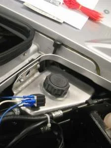
- Remove the coolant header tank and its bracket if you can, as the blocks are hard to reach. Make this connection before the charge cooler header tank goes in.
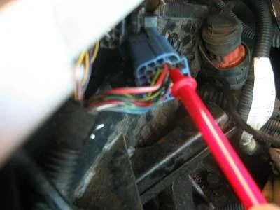
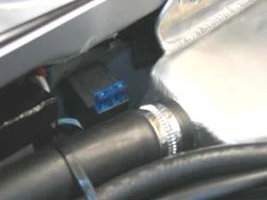
- There are two blocks: a black one on top, and the blue one you want below it. In the blue block, find the red wire with a grey stripe. It is thicker than most of the others, and is on the top (the side with the push-release catch), on the left-hand side of the wires entering the block from the rear of the car.
- Test it with a meter to check it stays live for 45 seconds after the ignition is turned off. This needs two people: one to test, one to switch the ignition. Turning the ignition on and off only keeps it live for five or six seconds. You have to start the engine and then switch off to get the 45 seconds.
- Connect it to terminal 86 of the relay. Rather than cutting the wire, strip a short length of the red/grey wire, bind the relay feed wire on, solder the join, and insulate it with tape.
- Mount the relay where it is protected from the weather: on the rear boot bulkhead near the top, under the lip to the right of the header tank (bulkhead centre). Run the feed wire around the corner by the ECU and secure it to the boot release cable sheath, which runs behind the header tank.
- Run the positive feed from the battery up and around the top of the rear wheel arch, and along the boot bulkhead from the offside to terminal 30 of the relay. Somewhere on this run (about the middle of the wheel arch) prepare the battery negative wire for the pump negative.
- Run a blue wire from terminal 87 to the pump positive, and a black wire from terminal 85 to earth. A convenient earth is on the left-hand side of the inlet manifold, viewed from the rear, about a foot from the relay.
- If your relay has an integral 30 amp fuse, change it for a lower value: 15 amp.
- Fit the header tank, pump and hoses before making the final connections. Wait to connect the relay positive and the battery negative to the pins in the pump plug until the pump is in place, so you can get the wire lengths right. Check which way round the plug goes against the + and - marked on the pump before you take it out to fit the pins.
- Tape everything up and tie the wires. The pump plug is just behind the wheel arch liner, where indirect moisture gets in, so the author also taped over the plug connection itself.
- Make the battery connections.
One owner's fit and what others added (2007 to 2015)
The pump should only run with the engine. How owners wired it, in the order they reported it:
- Battery feed and a relay, switched from the fuelling circuit (2007, Turbo). The author ran a fused positive and a negative cable from the battery, through the sill with the hoses, because he didn't know the pump's current draw. The pump has no wattage or amps on it or on the box, and the maker confirmed 17 amp cable was adequate. The relay is switched from the red/grey wire in the blue connector block behind the coolant expansion tank bracket. The terminal numbers and the full procedure are in the kit sheet notes above. This circuit stays live for 45 seconds after switch-off, but only if you have started the engine. Turning the ignition on and off alone gives five or six seconds.
- Other ways of wiring it (2009 and 2015, supercharged cars). One owner took the feed through the fuse box and a spare relay position in the boot, and another suggested using the wire that feeds the fuel pump relay coil. Both are in the supercharged car notes.
The author's relay had a 30 amp fuse that he replaced with a 15 amp one. Another owner planned a 5 amp fuse (see the fan switch below). Neither figure is confirmed, so decide the fuse value from your own wiring.
Fan wiring
The maker's fitting sheet (Courtenay Sport, 2008)
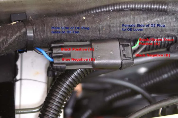
The two Spal fans have 2-pin connectors that don't fit the original wiring plug. The best option is to cut the connectors off the Spal fans, cut the original plug off the original fan (leaving enough wire to solder to), and solder the Spal wires to the original plug, with the polarity right. If you get it wrong, the fans will run the wrong way when they cut in.
- Spal fans: blue is positive, black is negative.
- Car side of the original 2-pin plug (female): positive is black with a green trace, and negative is black.
- Fan side of the original plug (male): a blue wire and a black wire, marked A (black, positive) and B (blue, negative). This is the opposite way round from the Spal fans.
Connect positive to positive and negative to negative. The black/green goes to the blue of the Spal fans, and the black goes to the black. Do not just join the blue and black from the original plug to the Spal fans without checking first, or the polarity will be wrong. The author suggests swapping the blue and black pins in the fan side of the plug, by carefully easing the pins out of the socket with a small screwdriver, so that blue is positive and black is negative to match the Spal fans. That is optional.
Solder every connection and insulate it with heat shrink, and check that nothing rubs or catches when the radiator assembly goes in.
One owner's fit and what others added (2007 and 2009)
The new Spal fans have blue and black wires, as does the original fan plug. The first author joined blue to blue and black to black, and tested the fans with an old battery and a sheet of paper on the radiator. They blew the paper off, so he assumed they were right. Several things then went wrong, in this order:
- A second owner connected blue to blue and black to black and found the fans blew the wrong way. He thought it might be luck of the draw with how the car was made.
- The first author then tested his own fans properly, by triggering them from the car, and found they were wrong too. The bench test with a battery had only shown the polarity he had assumed. Blade pitch matters as well as polarity, so only a real test on the car tells you.
- The fix, reported by several owners in 2007 and 2009, on both Turbo and supercharged cars, is that the blue and black wires cross over: the blue wire on the new fan loom goes to the black wire on the car loom, and the other way round. The easy way is to ease the two pins out of the original fan plug and push them back in the opposite holes, so the colours still match. The plug works like the pump plug, so the pins pull out.
- One owner said the Pro Alloy radiator's own wiring is a straight plug-in. That is the radiator, not the pre-rad fans.
The fan leads come out of the front. The leads on the pre-rad as supplied were on the front side of the housing, and the original fan connects through a hole at the rear, about a third of the way in from the nearside. The author turned his fans round so the leads came out the right side, which meant drilling a new hole in the housing for both leads (one was too short for the old hole). A second owner found the same thing. Taping over the old hole and replacing the grommet worked, though the grommet needed trimming. Fit stainless nyloc nuts and wax the fan studs while you are there.
Testing the fans. The coolant temperature sensor is on the nearside of the engine block, under a black plate that carries loom wiring, next to a square-headed block drain plug. Only the brass part is visible, and the plug is out of sight below the plate. Unplugging the sensor, or removing it, makes the fans run when the ignition is switched on, so you can see which way they blow. The author then found the fans stayed on all the time after he plugged it back in, and had to take out fuse 8 for 15 minutes to let the ECU reset. That is one owner's experience, so check the fuse numbering for your car before you pull anything.
Fan switch. One owner measured the pump at 0.88 amps in normal running, found each Spal fan is rated at up to 7.9 amps, and added a switch in the driver's cubby hole to run the fans by hand, tapped into the same supply cable as the pump. He said the temperatures fell as soon as the fans came on. He also planned to swap the 15 amp relay fuse for a 5 amp one, which doesn't obviously add up with two fans on the same supply, so work out the loads and fuse sizes for your own wiring before copying it.
The rest of the fitting is in Pro Alloy charge cooler: fitting to a Turbo and Turbo charge cooler kit: parts, hoses and fixings. For how the Turbo's cooling circuit behaves see Turbo cooling circuit and upgrades.