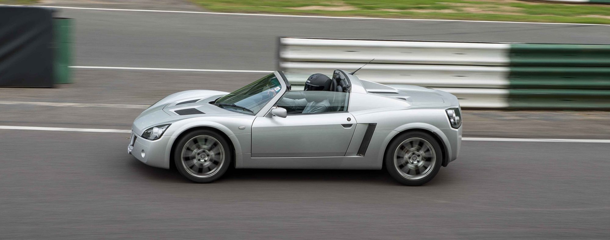
The steps below are shortened from the Vauxhall TIS pages for the Speedster. The VX220 shares the same engines and most of the car, but check anything unusual against your own car. The TIS pictures and the full wording aren't reproduced, so use the workshop manual if you are doing the job. We haven't seen owners' accounts of this job, so there are no owner tips here.
A long job with many connections to disconnect. The page lists the steps for the Turbo in order.
The engine and gearbox come out as a unit. Support the weight properly and use a hoist rated for it.
Install new blanking plug to open connections on fuel rail. Do not install previously used blanking plug.
End of track control arm locates into chassis. Ensure correct new locking nut is used. Early type have coarse thread, later type have fine thread.
Engine and gearbox removal and installation
Turbo (Z20LET) only.
Remove
- Raise vehicle
- Remove engine undertray (Remove 13x bolt, 13x washer)
- Remove exhaust pipe undertray (Remove 12x bolt, 12x washer, 2x clip)
- Drain coolant system
- Position collecting container
- Remove lower hose from radiator feed hose
- Remove collecting container when drained (Release clip)
- Drain transmission fluid (Position collecting container; Remove drain plug; Install new sealing ring; Replace drain plug when drained 35)
- Release support bracket for auxiliary cooling pump (Remove nut)
- Lower vehicle
- Disconnect battery negative lead
- Release windscreen washer bottle position to one side
- Release bolt, nut
- Remove engine cover (Apply match mark to engine cover 2x hinge; Remove 6x bolt, 6x washer, 2x shim)
- Disconnect harness connector from mass air flow meter, temperature sensor
- Disconnect air intake hose from air cleaner housing (Release clip)
- Disconnect engine breather hose from air intake hose (Release clip)
- Disconnect air intake hose from turbocharger (Release clip)
- Remove support bracket for air intake hose and lifting eye from engine (Remove bolt)
- Disconnect aeration hose from engine (Release clip; Release hose from bulkhead; Position hose to one side)
- Disconnect coolant top hose from engine (Release clip)
- Disconnect vacuum hose from turbocharger (Pull off)
- Disconnect engine harness from body harness, right side of engine compartment (Disconnect 2x connector)
- Disconnect air intake hose from throttle body (Release clip)
- Disconnect vacuum hose from vacuum unit of switchover valve
- Pull off
- Remove, then discard cable tie (Release clip)
- Disconnect vacuum hose from throttle body housing (Release clip; Release clip)
- Disconnect coolant overflow hose from engine assembly (Release clip)
- Release fuel pressure from fuel rail
- Remove cap from pressure relief valve
- Install fuel Pressure Test Equipment KM-J34730-91 to pressure relief valve
- Position collecting container
- Bleed pressure from fuel rail at pressure relief valve
- Remove fuel Pressure Test Equipment KM-J34730-91 from pressure relief valve (Remove collecting container; Install cap to pressure relief valve)
- Release fuel feed hose from fuel rail (Release union)
- Release fuel return hose from fuel rail (Release union)
- Disconnect vacuum hose for brake servo from inlet manifold (Release integral clip)
- Disconnect lower coolant hose from coolant expansion tank (Release clip)
- Remove coolant expansion tank from support bracket (Release clip; Release harness connector for level sensor)
- Disconnect hose of distribution housing from auxiliary coolant pump (Release clip)
- Disconnect lower coolant hose from oil cooler and throttle body (Release 2x clip)
- Disconnect body/engine harness from support bracket of expansion tank (Disconnect harness connector)
- Release harness from coolant hose (Remove, then discard 4x cable tie)
- Disconnect earth cable of body harness from inlet manifold (Remove bolt; Remove, then discard cable tie)
- Disconnect main engine harness from body harness, left side of engine compartment (Disconnect 4x connector; Move harness to engine)
- Disconnect and remove auxiliary coolant pump and bracket from vehicle (Release bolt from transmission housing; Disconnect connector; Release clip)
- Disconnect clutch slave cylinder
- Release spring clip
- Position to one side (Position to one side Note: Fluid leaks, use collecting container.)
- Disconnect lower coolant hose from distribution piece (Release clip)
- Disconnect turbocharger coolant hose from lower coolant hose (Release clip; Release 2x clip)
- Release 2x gearshift cable (Release 2x spring clip; Position to one side)
- Raise vehicle to suitable working height
- Remove 2x rear road wheel
- Use special socket located under front bonnet
- Remove 8x wheel bolt
- Remove, hub nut for left rear wheel (Remove split pin, nut, washer)
- Release left drive shaft from hub
- Disconnect left ABS harness from ABS sensor (Release integral clip; Release 2x clip)
- Release left brake hose clip from lower wishbone (Release locking nut)
- Release left brake cable from left brake caliper
- Remove left brake caliper from left disc hub (Remove 2x bolt; Position, then support caliper to one side)
- Disconnect track control arm, left from chassis (Release lock nut for track control arm)
- Release left carrier for upper ball joint from left wheel hub (Release 2x bolt; Release 4x shim and bracket for ABS sensor)
- Release left lower wishbone from chassis (Release locking tag)
- Release left shock absorber from chassis (Remove bolt, nut)
- Remove left rear disc hub, shock absorber, track control arm, lower wishbone assembly Note: 2x technician required.
- Remove left driveshaft from vehicle
- Remove right rear disc hub, shock absorber, track control arm, lower wishbone assembly (Follow sequence for left side)
- Release oxygen sensor harness from left rear chassis (Release 2x clip)
- Release oxygen sensor harness from heat shield for catalytic converter (Release clip; Position to rear of vehicle)
- Raise vehicle
- Remove secondary catalytic converter for exhaust
- Remove 3x front nut, then discard
- Remove 3x rear nut, then discard
- Release rubber mount bracket
- Release rubber mount
- Remove gasket from front joint, then discard
- Release 2x gearshift cable from engine support bracket (Position 2x cable to one side)
- Remove intake air hose from intercooler and turbocharger (Release 2x clip; Remove, then discard cable tie)
- Release tension from and remove ribbed V-belt
- Remove idler pulley assembly for ribbed V-belt (Remove 3x bolt)
- Remove right driveshaft heatshield for rear engine mount (Remove 3x bolt, 3x washer)
- Disconnect right body harness from alternator (Remove 2x nut, 2x washer)
- Disconnect body harness connector from oil pressure sensor
- Release body harness from support bracket for oil pipe (Remove clip)
- Release body harness from support bracket for vacuum tank (Remove clip)
- Disconnect body harness from starter motor (Remove 2x nut, 2x washer)
- Disconnect earth of body harness from engine block (Remove bolt)
- Disconnect harness connector from switchover valve for intake manifold
- Disconnect harness connector from reverse light switch
- Lower vehicle
- Release body harness from transmission bracket (Release 2x clip; Position harness to one side)
- Remove upper 2x bolt from reaction mount bracket, lower, at front of chassis
- Release upper engine mount, right (Remove 3x bolt)
- Release upper engine mount, left (Remove 3x bolt)
- Raise vehicle
- Install and set Engine Support Tool KM-6054, use with Adapter KM-904 (Support engine weight)
- Remove lower reaction mount, rear, from between transmission and rear chassis (Remove centre bolt and nut; Remove 3x bolt and washer)
- Remove lower reaction mount, front, from between transmission and front chassis (Remove centre bolt and nut; Remove 2x bolt)
- Remove reaction mount bracket from lower front chassis (Remove 2x bolt)
- Remove engine and transmission from vehicle
Install
- Install engine and transmission to vehicle
- Install reaction mount bracket, to lower front chassis
- Recut 2x bolt thread, use recommended locking compound if not
- Install 2x lower bolt hand tight
- Install reaction mount, lower front, to between transmission housing and front chassis
- Recut 2x bolt thread, use recommended locking compound if not
- Install 2x bolt hand tight
- Install new engine mount centre bolt and nut hand tight
- Install reaction mount, lower rear, to between transmission and rear chassis
- Recut 3x bolt thread, use recommended locking compound if not
- Install 3x bolt, washer hand tight
- Install new engine mount centre bolt, nut hand tight
- Remove Engine and Transmission Support Tool KM-6054 with Adapter KM-904
- Lower vehicle
- Install upper engine mount, left
- Recut 3x bolt thread, use recommended locking compound if not
- Install 3x bolt, hand tight
- Install upper engine mount, right
- Recut 3x bolt thread, use recommended locking compound if not
- Install 3x bolt, hand tight
- Install lower reaction mount bracket, front, 2x bolt
- Recut 2x thread, use recommended locking compound if not
- Install 2x bolt, hand tight
- Secure engine mount bolt, right upper (Secure 3x bolt 49 Nm)
- Secure engine mount bolt, left upper (Secure 3x bolt 49 Nm)
- Position body harness to transmission bracket (Install 2x clip)
- Raise vehicle
- Secure reaction mount bracket, lower front (Secure 2x bolt 25 Nm)
- Secure reaction mount bracket, lower front (Secure 2x bolt 49 Nm; Secure centre bolt, nut 86 Nm)
- Secure reaction mount bracket, lower front (Secure 2x bolt 49 Nm; Secure centre bolt, nut 86)
- Secure reaction mount bracket, lower rear (Secure 3x bolt 49 Nm; Secure centre bolt, nut 86 Nm)
- Connect body harness connector to reversing light switch
- Connect body harness connector to switchover valve for intake manifold
- Connect body harness earth to engine block (Install bolt)
- Connect body harness to starter motor (Install 2x washer, 2x nut)
- Install body harness to support bracket for vacuum tank (Install clip)
- Install body harness to support bracket for oil pipe (Install clip)
- Connect body harness connector to oil pressure sensor
- Connect body harness to alternator (Install 2x washer, 2x nut)
- Install right driveshaft heatshield to rear reaction mount (Install 3x washer, 3x bolt)
- Install idler pulley assembly for ribbed V-belt (Install 3x bolt 20 Nm)
- Install ribbed V-belt, then apply tension - see “Ribbed V-belt Tension, Check”
- Connect intake air hose to intercooler and turbocharger (Install new cable tie)
- Install auxiliary coolant pump to transmission housing (Secure nut)
- Install secondary catalytic converter for exhaust (Install new gasket to front joint; Position bracket for rubber mount; Install 3x new rear nut; Position rubber mount)
- Connect harness connector for auxiliary pump
- Lower vehicle
- Secure reaction mount bracket, lower front (Install 2x bolt 25 Nm)
- Secure auxiliary coolant pump to transmission housing (Secure bolt)
- Raise vehicle to suitable working height
- Install harness to rear silencer heatshield for oxygen sensor installed to secondary catalytic converter (Secure clip to heatshield; Install harness to subframe; Secure 2x clip)
- Install left driveshaft
- Install left rear disc, hub, shock absorber, control arm and lower wishbone assembly Note: 2x technician required.
- Secure left shock absorber to chassis (Install bolt, nut 45 Nm)
- Secure left lower wishbone to chassis (Install front bolt, nut 65 Nm; Install new locking tag to nut)
- Install end of track control arm to left chassis (Secure new locking nut 65 Nm)
- Install ball joint carrier, left upper, to lower wishbone assembly
- Install 4x shim and bracket for ABS sensor connector
- Recut 2x bolt thread, use recommended locking compound if not
- Secure 2x bolt 45 Nm
- Install brake caliper to left disc hub (Secure upper bolt 45 Nm; Secure lower bolt 25 Nm)
- Install left brake cable to left brake caliper
- Install brake hose clip to lower wishbone (Secure new locking nut 9 Nm)
- Connect harness connector to left ABS sensor (Install connector; Install 2x clip)
- Install washer, hub nut for left rear wheel
- Install right rear disc, hub, shock absorber, control arm and lower wishbone assembly (Follow sequence for left side)
- Secure 2x rear wheel hub nut 235 Nm (Install 2x new split pin)
- Install 2x rear road wheel (Tighten 8x bolt, 2x security bolt 90)
- Lower vehicle
- Install 2x gearshift cable (Install 2x ball socket; Install 2x spring clip)
- Install turbocharger coolant hose to coolant bottom hose (Install clip; Secure to fuel filter pipe; Secure 2x clip)
- Connect coolant lower hose to distribution housing (Install clip)
- Install coolant main lower hose to oil cooler (Install clip)
- Install clutch slave cylinder, pipe (Install spring clip; Install bracket, push fit)
- Install auxiliary coolant pump hose to distribution housing (Install clip)
- Connect body harness to switchover valve for intake manifold (Connect harness connector)
- Connect main engine harness to main body harness, left side of engine compartment (Connect 4x harness connector)
- Connect body harness earth to inlet manifold (Secure bolt; Secure cable tie)
- Install harness to coolant hose (Install 4x new cable tie)
- Connect body engine harness to support bracket for expansion tank (Connect harness connector)
- Connect coolant hose for auxiliary pump to distribution housing (Install clip)
- Install coolant expansion tank to support bracket (Install clip; Install harness connector for level sensor; Secure integral clip)
- Connect coolant lower hose to expansion tank (Secure clip)
- Connect vacuum hose for brake servo to inlet manifold (Secure integral connector)
- Install fuel return hose to fuel rail (Secure union)
- Install fuel feed hose to fuel rail (Secure union)
- Connect coolant overflow hose to engine assembly (Install clip)
- Connect vacuum hose to throttle body housing (Install 2x clip)
- Connect vacuum hose to vacuum unit of switchover valve (Push fit; Secure vacuum hose to alternator bracket; Install new cable tie)
- Connect upper intercooler hose to throttle body (Install clip)
- Connect engine harness from body harness, right side of engine compartment (Connect 2x connector)
- Connect vacuum hose to turbocharger (Push fit)
- Connect upper coolant hose to throttle body (Install clip)
- Connect aeration hose to engine
- Install air support bracket, air intake hose for lifting eye to engine
- Recut bolt thread, use recommended locking compound if not
- Install bolt
- Install air intake hose assembly to between air cleaner and turbocharger (Install 2x clip)
- Connect engine breather hose to air intake hose (Install clip)
- Install air intake hose to air cleaner housing (Install clip)
- Install mass air flow meter, temperature sensor connector (Connect harness connector)
- Bleed clutch - see “Hydraulic Clutch, Bleed” Note: 2x technician required.
- Install engine cover (Align match marks for 2x hinge; Install 2x shim, 6x washer, 6x bolt)
- Connect battery negative lead (Secure bolt, nut; Secure windscreen washer bottle)
- Raise vehicle
- Replenish transmission fluid (Fill to level of plug aperture)
- Connect lower hose for radiator feed (Secure clip; Install new cable tie)
- Lower vehicle
- Replenish coolant fluid - see “Cooling System, Drain, Fill and Bleed”
- Program all volatile memories
- Run engine and check for leaks (Switch off engine when complete)
- Raise vehicle
- Install exhaust pipe undertray (Install 12x bolt, 12x washer, 2x clip)
- Install engine undertray (Install 13x bolt, 13x washer)
- Lower vehicle
Owners' experience
What owners said in forum threads in 2012 and 2020. It is advice from people who did the job, not a procedure. The NA owners' notes on the water pump bolt, the oil pump and the order of work are in Engine removal and installation (NA), but the Turbo has its own fittings, so don't assume they carry over.
- Take the gearbox with it. Two owners said that if the engine is coming out, drop it with the gearbox attached. It is much easier to split and rebuild the two off the car and put them back as one piece. This was also the advice in 2012 for an NA with the clam off.
- Engine alone, with the oil pump and inner cam belt cover left on. In 2020 one owner asked whether the Turbo engine can come out on its own, to avoid pulling the driveshafts, with the cover and oil pump in place. One reply was simply "yes". The other, from someone who had done it, said it is possible but very tight, and he didn't recommend it. The asker had done it before with the head, oil pump and inner cover off, which gave more room. We have no more detail than that.
- Through the top with the clam on. The same owner once swapped an LET for an LEH engine from above with the clam on, because of restrictions in his garage. He said it is not the best option.