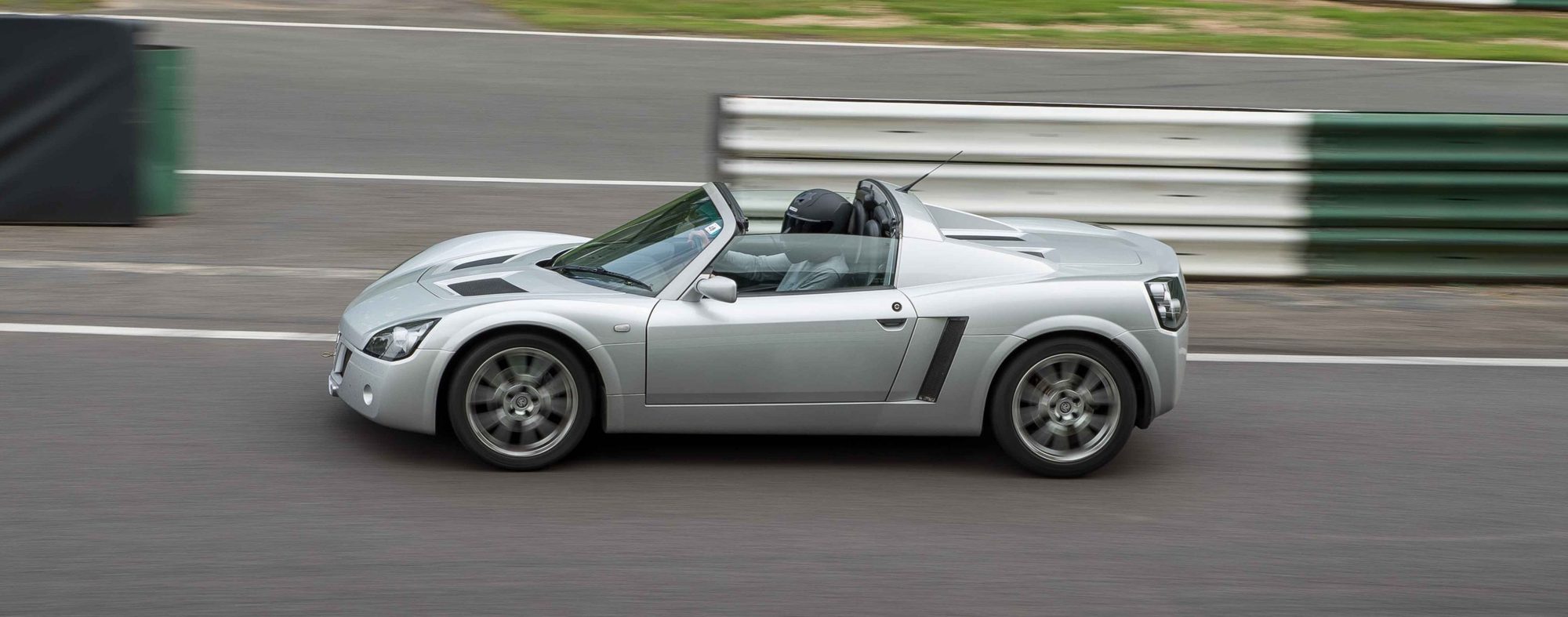
The steps below are shortened from the Vauxhall TIS pages for the Speedster. The VX220 shares the same engines and most of the car, but check anything unusual against your own car. The TIS pictures and the full wording aren't reproduced, so use the workshop manual if you are doing the job. We haven't seen owners' accounts of this job, so there are no owner tips here.
Engine-out work. Clearances are on Turbo engine data and torques on Torque values.
Thinking of removing the balancer shafts? Owners' experience, the Turbo kit and the NA method are in Balancer shaft deletion: what owners did on the Turbo and NA.
A four post hoist must be used to raise the vehicle when removing the engine undertray and exhaust pipe undertray. The vehicle can be moved to a two post hoist for other operations if required.
Other jobs from the same factory chapter: Crankshaft and bearing clearances (Turbo); Crankshaft seals, pulley, sprocket and pulse sensor (Turbo); Pistons, con-rods and piston rings (Turbo).
Balancer shaft unit
Turbo (Z20LET) only.
Remove
- Remove engine undertray (Raise vehicle; Remove 13x bolt, 13x washer)
- Remove exhaust pipe undertray (Remove 12x bolt, 12x washer, 2x clip)
- Lower vehicle
- Disconnect battery negative lead
- Release windscreen washer bottle, then position to one
- Release bolt, nut
- Release intercooler hose from throttle body (Release clip)
- Disconnect oxygen sensor harness from engine harness (Release integral clip; Remove, then discard cable tie)
- Release harness from chassis (Release 2x clip)
- Release harness from heatshield (Release clip)
- Remove oil level dipstick (Pull off)
- Release rear road wheel from right side
- Use special socket located under front bonnet
- Release 4x wheel bolt
- Raise vehicle
- Drain engine oil (Position collecting container; Remove drain plug; Remove, then discard O ring)
- Lower vehicle to suitable working height
- Remove rear road wheel from right side (Remove 4x bolt, security bolt)
- Remove right rear wheel arch liner (Remove 4x screw, 2x clip)
- Remove intercooler hose from intercooler (Release; Remove, then discard 4x cable tie)
- Remove toothed belt upper cover (Remove 2x bolt)
- Remove ribbed V-belt
- Using suitable spanner rotate tensioner clockwise, then (Using suitable spanner rotate tensioner clockwise, then Install suitable locking pin)
- Remove crankshaft pulley
- Apply match marks
- Use spanner to counter-hold centre nut on crankshaft (Use spanner to counter-hold centre nut on crankshaft sprocket)
- Remove toothed belt lower cover (Remove 2x bolt)
- Rotate crankshaft in normal direction of rotation to Top Dead Centre (TDC) on cylinder no. 1, until timing marks are aligned
- Raise vehicle
- Remove secondary catalytic converter for exhaust
- Remove 3x front nut, then discard
- Remove 3x rear nut, then discard
- Release rubber mount bracket
- Release rubber mount
- Remove gasket from front joint, then discard
- Install engine support to engine assembly
- Remove heat shield from rear engine mount (Remove 2x bolt from rear engine mount; Remove bolt from engine cylinder block)
- Remove engine support from engine assembly
- Release lower oil pan from upper oil pan Note: Support lower oil pan when removing to avoid damage to harness for oil level sensor. (Remove 16x bolt)
- Release oil level sensor from oil pan (Remove 2x bolt; Remove, then discard oil pan gasket)
- Disconnect engine harness from oil level sensor (Release integral clip)
- Remove upper oil pan from vehicle (Remove 18x bolt; Remove, then discard gasket)
- Remove oil pick up pipe from engine (Remove 2x bolt from oil pump; Remove 2x bolt from balancer shaft unit; Remove, then discard O ring)
- Remove balancer shaft unit from engine (Remove 15x bolt; Remove shim)
Install
- Install balancer shaft unit to engine (Install 15x bolt 20 Nm + 45°; Clean mating surfaces)
- Install oil pick up pipe to engine (Install 2x bolt to oil pump 8 Nm; Install 2x bolt to balancer shaft unit 8 Nm; Install new O ring)
- Install upper oil pan to engine
- Install 18x bolt 20 Nm
- Apply bead of adhesive sealant compound to rear crankshaft
- Install new gasket
- Connect engine harness to oil level sensor (Secure integral clip)
- Secure oil level sensor to lower oil pan (Install 2x bolt 8 Nm)
- Install lower oil pan to upper oil pan (Install new oil pan gasket; Install 16x bolt 8 Nm)
- Install drain bolt 10 Nm (Lubricate new O ring)
- Install engine support to engine assembly
- Remove 2x bolt from rear engine mount
- Install heat shield to rear engine mount
- Apply locking compound (Recut 2x bolt thread)
- Secure bolt to engine cylinder block
- Remove engine support from engine assembly
- Secure rear engine mount (Secure 2x bolt 46 Nm)
- Install secondary catalytic converter for exhaust
- Install 3x new front nut
- Install 3x new rear nut
- Install rubber mount bracket to flange bolt
- Secure rubber mount
- Install gasket to front joint
- Install toothed belt lower cover (Install 2x bolt 6 Nm)
- Install crankshaft pulley (Align match marks; Counter hold centre nut)
- Install ribbed V-belt
- Using suitable spanner rotate tensioner clockwise, then remove (Using suitable spanner rotate tensioner clockwise, then remove suitable locking pin)
- Lower vehicle to suitable working height
- Install toothed belt upper cover (Install 2x bolt 6 Nm)
- Install intercooler hose to intercooler (Secure clip; Install new 4x cable tie)
- Install right rear wheel arch liner (Install 4x screw, 2x clip)
- Install rear road wheel to right side (Install 4x bolt, security bolt; Do not tighten)
- Lower vehicle
- Secure rear road wheel (Tighten 4x bolt, security bolt 90)
- Install oil level dipstick (Push fit)
- Secure intercooler hose to throttle body (Secure clip)
- Connect oxygen sensor harness from engine harness (Secure integral clip; Install new cable tie)
- Secure harness to chassis (Secure 2x clip)
- Secure harness to heatshield (Secure clip)
- Connect battery negative lead (Secure nut, bolt; Secure windscreen washer bottle)
- Program all volatile memories
- Fill engine to correct oil level
- Start and run engine until oil light goes out
- Check oil level, adjust if necessary
- Install engine undertray (Raise vehicle; Install 13x bolt, 13x washer)
- Install exhaust pipe undertray (Install 12x bolt, 12x washer, 2x clip)
- Lower vehicle
Balancer shaft backlash
Turbo (Z20LET) only.
Remove
- Remove upper oil pan, see “Oil Pan, Upper, Replace”
- Remove oil pick up pipe from engine (Remove 2x bolt from oil pump; Remove 2x bolt from balancer shaft unit; Remove, then discard O ring)
- Remove front baffle plate from balancer shaft unit (Remove 2x bolt)
- Install Screw Measuring Device KM-949
- Set measuring arm to 9 o'clock position
- Install short knurled bolt to balancer shaft unit
- Set dial gauge to zero
- Measure balancer shaft unit, tooth backlash
- Toothed backlash must be measured in 4 different locations
- Permissible backlash 0.02 mm to
- Use knurled bolt to rotate shaft
- Remove balancer shaft unit from engine (Remove 15x bolt; Remove shim)
- Check identification number against table (One shim only to be used)
Install
- Install balancer shaft unit to engine (Install shim; Clean all mating surfaces)
- Install Screw Measuring Device KM-949 (Set measuring arm to 9 o'clock position; Rotate shaft; Set dial gauge to zero)
- Measure balancer shaft unit, tooth backlash
- Toothed backlash must be measured in 4 different locations
- Permissible backlash 0.02 mm to
- Remove Screw Measuring Device KM-949 from balancer shaft unit
- Install oil pick up pipe to engine (Install 2x bolt to oil pump; Install 2x bolt to balancer shaft unit; Install new O ring)
- Install front baffle plate to balancer shaft unit (Install 2x bolt 8 Nm)
- Install upper oil pan, see “Oil Pan, Upper, Replace”